Testing the Pantograph Power
Pantograph Load Testing for Electric Trains
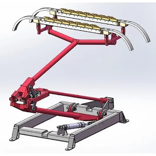
A pantograph load test machine is a specialized system used to evaluate and simulate the performance of pantographs, which are critical components in electric trains.
Complex Environment and Challenges
- The pantograph is the component of an electric train that makes contact with the overhead trolley wire (catenary system) to draw power.
- The environment where the pantograph touches the wire is incredibly complex:
- Catenary systems exhibit varying vertical stiffness along their length.
- The wires zigzag at intervals (typically 30 to 100 meters) to prevent grooving.
- The force applied by the pantograph to the wire must stay within a well-defined range (usually between 70N and 120N).
- Too little force results in loss of contact, arcing, and damage to the wire and contact bar.
- Too much force causes premature wear on the wire and contact bar due to friction.
- Delivering the right amount of force requires variable vertical motion, especially at high speeds.

Testing Challenges:
- Recreating the dynamic pantograph environment in the lab is complex:
- Pantographs travel at speeds up to 350 kph (220 mph) and carry enough power to accelerate heavy rail cars.
- Traditional spin/slide tests using spinning discs and carbon specimens do not fully replicate real-world dynamics.
- These tests involve pushing a piece of carbon against a spinning wire, but they lack the full complexity of actual pantograph operation.
Advanced Testing Systems:
- New pantograph testing systems aim to simulate operational dynamics more precisely.
- These systems measure various parameters, including:
- Contact forces: Load cells allow precise measurement of the forces exerted by the pantograph.
- Lateral movement: Motor servo-actuators reproduce the catenary stagger, allowing to travel pantograph to achieve its maximum height up to 4000mm with respect to the central axis of the pantograph.
- Frequency and acceleration: The system can operate at frequencies up to 1.5 Hz and accelerations of up to 2.7 g.
- The goal is to understand the interaction between the pantograph and catenary system accurately, ensuring safe and efficient rail operation.
TEST CASE
- Holding the pantograph in test in a fixed, known, repeated position near the testing machine
- Appling a pneumatic air to rise the pantograph lifting.
- Measuring
- Applied static load
- Distance traveled pantograph height
- Observation and Adjustment of the pantograph by Graph with in the limits.
DESIGN
- Power supplies
- Cabinet
- Control Pc
- Servo drives
- Safety button
SOFTWARE
- Operator Login Interface
- Live data Graph Interface
- Settings Interface
FUTURE
The Adjustment of the pantograph fine turning error message pop up will be provided.


Comments
Post a Comment